Technical Design of the Plastic Extrusion Screw
A comprehensive guide to the engineering principles, design considerations, and performance criteria for the plastic extrusion screw, the critical component in plastic extrusion machinery.
1.3.4.1 Evaluation Criteria for the Plastic Extrusion Screw
Plasticating Quality
Plasticating quality refers to producing products that meet quality requirements, achieving specified physical, chemical, mechanical, and electrical properties with good surface quality. The plastic extrusion screw must meet user requirements for freedom from bubbles, crystal points, and uniform dye dispersion. Low-temperature extrusion is currently a developing trend in optimizing the plastic extrusion screw performance.
Production Output
Production output refers to the quantity or extrusion rate through a given die while ensuring plasticating quality. The efficiency of a plastic extrusion screw is often measured by its ability to maintain consistent output while preserving material properties, making this a key performance indicator for any plastic extrusion screw design.
Energy Consumption
Specific energy consumption refers to the energy consumed per kilogram of plastic extruded. This is generally expressed as P/Q, where P is power (kW) and Q is output (kg/h). A well-designed plastic extrusion screw minimizes this ratio while maintaining output quality, directly impacting operational efficiency and cost-effectiveness of the plastic extrusion screw system.
Adaptability
The adaptability of a plastic extrusion screw refers to its ability to process different plastics, match different dies, and produce various products. A versatile plastic extrusion screw can handle a range of materials and applications, reducing the need for multiple specialized screws and increasing production flexibility.
Manufacturing Feasibility
An effective plastic extrusion screw must also be easy to manufacture with a favorable cost-performance ratio. Complex designs that significantly increase production costs without corresponding performance benefits are generally impractical. The ideal plastic extrusion screw balances advanced performance characteristics with straightforward, cost-effective manufacturing processes.
1.3.4.2 Design Considerations for the Plastic Extrusion Screw
Material Characteristics and Initial Conditions
The plastic extrusion screw design must account for material properties, initial geometry, dimensions, and temperature conditions. For example, PVC and polyolefin materials have significantly different processing properties. The former is an amorphous plastic with high viscosity, sensitivity to temperature and shear force, and no distinct melting point. The latter are crystalline plastics with low viscosity and distinct melting points. Even for the same plastic, variations exist between manufacturers and batches, requiring the plastic extrusion screw to accommodate these differences.
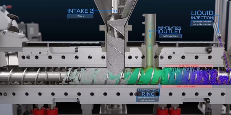
Fig. 1: Material behavior comparison in plastic extrusion screw processes
Die Geometry and Head Resistance Characteristics
The depth of the metering section channel must match the die characteristics for proper operation of the extruder, as seen in typical technical diagrams. For high-resistance dies, the metering channel should be shallower and the metering section longer. This critical matching ensures optimal performance of the plastic extrusion screw by balancing pressure development and material flow.
Heating/Cooling and Solid Conveying
According to solid conveying theory, when the barrel inner wall is processed into a cone with longitudinal grooves and the feed section is force-cooled, solid conveying efficiency can be improved. The plastic extrusion screw design must enhance the functions of the compression and metering sections to align the melting and melt conveying processes with feeding. Proper thermal management is essential for maintaining the plastic extrusion screw's efficiency and preventing material degradation.
Screw Rotational Speed
The rotational speed of the plastic extrusion screw primarily controls the shear rate during processing. Therefore, the linear speed of the screw outer diameter should meet specific conditions, varying with different materials. Higher speeds can increase output but may compromise mixing quality, creating a critical design balance for the plastic extrusion screw.
Optimal Speed Ranges for Common Materials
Specific Extruder Application
It is essential to clarify whether the extruder is used for product forming, compounding, pelletizing, or feeding. Different applications require different plastic extrusion screw designs. For example, a plastic extrusion screw designed for compounding may prioritize mixing elements, while one for profile extrusion focuses on pressure stability and uniform melt delivery.
1.3.4.3 Design of the Conventional Three-Section Plastic Extrusion Screw
The conventional three-section plastic extrusion screw has played an important role in the development of extruders, with some design concepts still in use today. This design philosophy connects the feed section with melt conveying, making the melting process critical to evaluating plastic extrusion screw design. It requires in-depth understanding of the extrusion process and relies on extensive practical experience.
To increase extruder output, increasing the plastic extrusion screw speed is generally used, but this can lead to poor plasticization or melt overheating, exacerbating extrusion process fluctuations—limitations of conventional screws. Developing new plastic extrusion screw designs is essential to address these issues. For example, a 90mm diameter plastic extrusion screw for PP processing has increased production capacity fourfold, reaching 600kg/h.
The conventional three-section plastic extrusion screw, typically with single-start threads, includes the following design aspects:
1. Determination of Screw Diameter (D)
The diameter of the plastic extrusion screw represents the production capacity of the extruder. National standards specify extruder diameter series. Large cross-section products require larger diameter extruders, and vice versa.
Empirical Relationship Between Screw Diameter and Product Size
| Screw Diameter (mm) | Pipe Diameter (mm) | Blown Film Diameter (mm) | Sheet Width (mm) |
|---|---|---|---|
| 30 | 3~30 | 50~300 | 10~45 |
| 65 | 20~65 | 400~900 | 400~800 |
| 90 | 30~120 | 700~1200 | 700~1200 |
| 120 | 50~180 | 1000~1400 | 1000~1400 |
| 150 | 80~300 | 1200~2500 | 1200~2000 |
| 200 | 120~400 | - | 2000~3000 |
2. Determination of Screw Length-to-Diameter Ratio (L/D)
The length-to-diameter ratio is a critical parameter of the plastic extrusion screw, representing its plasticating capacity and quality. There is a trend toward increasing L/D ratios, which extends material residence time in the extruder and improves plasticating quality but also leads to inconsistencies in residence time, manufacturing difficulties, increased screw deflection, and accelerated wear.
Therefore, the L/D ratio selection should strive for high product quality and output with the smallest possible ratio. Currently, the maximum L/D ratio for single-screw extruders reaches 60, with most between 25~35.
Evolution of Plastic Extrusion Screw L/D Ratios
3. Length Distribution of Screw Sections
The length distribution of each section of the plastic extrusion screw relates to specific material properties. For the melting process, when barrel pressure is approximately 4MPa, test results show that PP begins to melt after about 8 pitches, HDPE after 4.5 pitches, and PS after only about 2.5 pitches.
Currently, the length settings for each section of the plastic extrusion screw are mainly based on experience, as shown in the table below:
| Plastic Type | Feed Section | Compression Section | Metering Section |
|---|---|---|---|
| Amorphous Plastics | 20%-30% | 45%~50% | 25%~30% |
| Crystalline Plastics | 40%~60% | (3~5)D | 30%~45% |
4. Channel Depth and Compression Ratio
The design logic for channel depth starts with the metering section channel depth (h). After determining h, the feed section depth is established based on material melting requirements. Theoretical and experimental research shows that a shallow metering section channel depth benefits melt pressure development, conveying stability, and mixing效果.
However, an excessively shallow channel reduces conveying capacity and can cause shear overheating that exceeds the plastic's shear tolerance, leading to thermal degradation or even burning. This is particularly prominent when processing materials like wood-plastic composites with a plastic extrusion screw.
Additionally, with the development of new plastic extrusion screw structures, there has been a trend toward increasing metering section channel depth in recent years. From the perspective of material stability, PVC has the poorest stability, while PA and PE perform better.
Based on experience, the following formula applies to the plastic extrusion screw:
In the formula, D is the plastic extrusion screw outer diameter. For smaller diameter screws, use larger h values, and vice versa. For more stable materials, use smaller h values, and vice versa.
5. Thread Cross-Section and Screw Tip Design
Thread cross-sections are either rectangular or sawtooth-shaped. If R₁ represents the fillet radius at the root of the thread pushing surface, and R₂ represents the fillet radius at the root of the thread dragging surface, experience suggests:
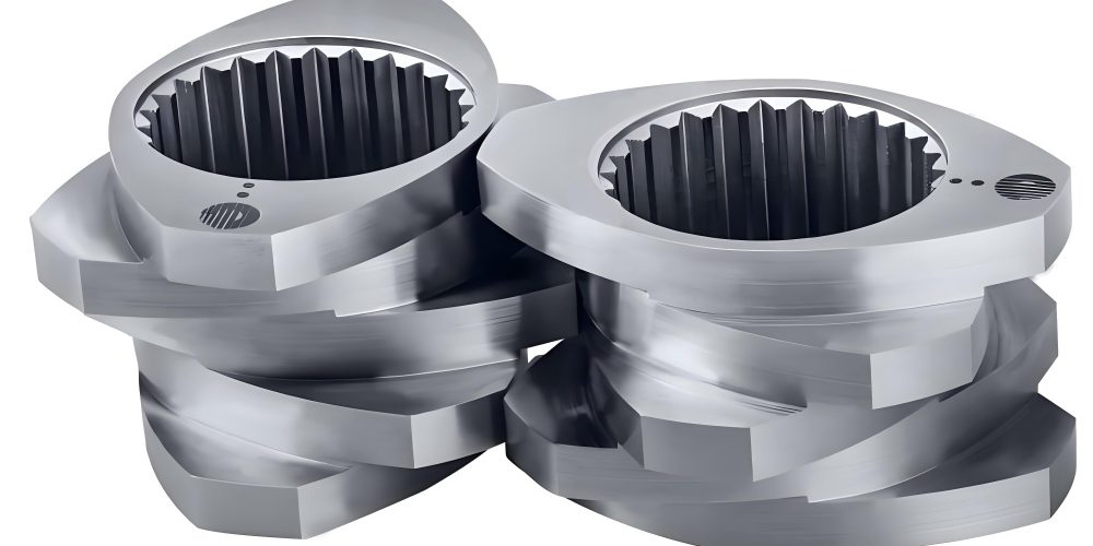
Fig. 2: Common thread profiles and tip designs for the plastic extrusion screw
Geometric Compression Ratios for Various Plastics
| Plastic Type | Compression Ratio (ε) |
|---|---|
| RPVC (pellets) | 2.5 (2~3) |
| RPVC (powder) | 3~4 (2~5) |
| SPVC (pellets) | 3.2~3.5 (3~4) |
| SPVC (powder) | 3~5 |
| PE | 3~4 |
| PP | 3.7~4 (2.5~4) |
| PS | 2~2.5 (2~4) |
| CA | 1.7~2 |
| PMMA | 3 |
| PET | 3.5~3.7 |
| PCTFE | 2.5~3.3 (2~4) |
| ABS | 1.8 (1.6~2.5) |
| POM | 4 (2.8~4) |
| PPO | 2 (2~3.5) |
| PC | 2.5~3 |
The spiral movement of the melt in the screw channel must transition to linear movement as it approaches the die. Proper selection of the tip shape ensures smooth flow into the die, avoiding stagnation and preventing local overheating and decomposition. Common plastic extrusion screw tips include spherical, conical (90°~140° angle—140° for free-flowing PA, 90°~120° for PVC),扇形, threaded cones (for cable extrusion), and asymmetric "歪头体" to prevent material stagnation and decomposition.
6. Screw and Barrel Clearance Determination
The plastic extrusion screw is cantilever-supported with a clearance fit between the screw and barrel. Clearance size significantly affects extruder output and energy consumption—excessive clearance dramatically reduces production capacity. Based on China's current technical level, national standards recommend clearance values for different diameter plastic extrusion screws.
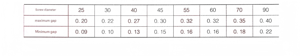
Fig. 3: Clearance specifications between plastic extrusion screw and barrel
Proper clearance is critical for the plastic extrusion screw's performance. Too small a clearance increases friction and wear, particularly with abrasive materials, while too large a clearance reduces pumping efficiency and increases backflow. The optimal clearance for a plastic extrusion screw depends on several factors including diameter, material characteristics, and operating conditions, with precision manufacturing ensuring these tolerances are maintained for consistent performance.