Single-Screw Extruder Operating Point Analysis
A comprehensive analysis of the interaction between extruder components and process parameters that determine the optimal performance of an extrusion line.
Die and Mold Components in the Extrusion Process
The die head serves as a subsequent component to the screw-based extrusion system, also known as the extrusion die. The mouth mold represents the final component of the die head assembly. The fundamental function of the die head is shaping, ensuring the product achieves the required form and dimensions.
In any extrusion line, the mouth mold stands as the critical component for achieving proper shaping. During the design process, several key considerations must be addressed to ensure optimal performance of the extrusion line.
These design considerations include facilitating easy assembly, disassembly, and cleaning; meeting mechanical strength and stiffness requirements; ensuring appropriate wear resistance and corrosion resistance; maintaining dimensional symmetry and uniform thickness where possible; creating smooth, streamlined flow channels; incorporating sufficiently long calibration sections; and achieving proper melt compression to ensure product density while eliminating defects like weld lines.
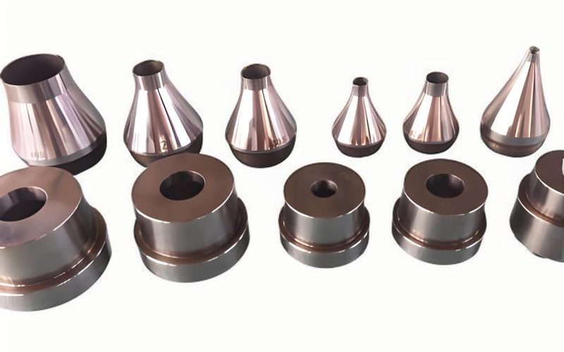
Figure 1: Die assembly components in a typical extrusion line
Critical Die Design Parameters
Wall Thickness Control
The uniformity of die wall thickness is typically achieved through adjustment bolts or thermally expanding bolts that provide automatic control. This precision is essential for maintaining product consistency in any high-quality extrusion line.
Temperature Control Requirements
Temperature control systems must maintain accuracy within 1°C to ensure proper melt flow characteristics and product quality. This level of precision is particularly critical in extrusion line applications where material properties are highly temperature-dependent.
Rheological Considerations
Die design must carefully consider rheological properties including shear thinning behavior, entrance effects, die swell, and melt fracture. These phenomena directly impact product quality and throughput in an extrusion line and must be addressed through proper channel geometry and surface finishes.
Die Characteristics and Flow Behavior
Die characteristics are commonly used to describe the relationship between throughput (Q) and pressure difference (Δp) across the die in an extrusion line. This fundamental relationship determines how the extrusion line will perform under various operating conditions.
Where:
- Q = Volume flow rate through the die, m³/s
- K = Die shape factor (dependent only on die dimensions, calculation methods shown in Table 1-8), m⁵
- Δp = Pressure drop of melt through the die, MPa
- μ = Viscosity of material in the die, Pa·s
This equation clearly demonstrates that extrusion throughput is directly proportional to the pressure difference across the die. In an actual production environment, the extruder serves as the power source while the die provides the resistance, forming an integrated system that collectively determines the production capacity of the extrusion line.
Figure 2: Pressure-flow characteristics in an extrusion line die
Die Shape Factor Calculations for Various Flow Channel Geometries
| Flow Channel Shape | Shape Factor Formula | Application in Extrusion Line |
|---|---|---|
| Cylindrical | πD⁴/128L | Rod and tube extrusion line applications |
| Plane Gap | WH³/12L | Sheet and film extrusion line processes |
| Annular Gap | πDh³/12L | Pipe and tube extrusion line production |
| Two Inclined Planes | W/6L(h₁ + h₂)(h₁² + h₂²) | Tapered profile extrusion line applications |
| Conical | 3πD'd³/128L(D² + d² + Dd) | Specialty profile extrusion line processes |
Table 1-8: Common die shape factor calculations for various extrusion line configurations
Extruder Operating Point Determination
Figure 3: Extruder operating diagram showing working points for different extrusion line configurations
In Figure 3, OD₁, OD₂, and OD₃ represent die characteristic lines. Comparison shows that OD₁ presents greater die resistance than OD₂, and so forth in the extrusion line. The diagram also illustrates the method for determining the operating point C of the extruder when using the OD₁ die at a screw speed of n₁. At this operating point, the pressure difference is pC and the throughput is QC.
Identifying the effective operating range of an extrusion line requires ensuring good plasticization quality, effective melt temperature control, and minimum economic throughput, among other considerations. These factors necessitate adjusting process conditions based on the extruder's performance characteristics.
The effective operating range is shown as the shaded area in Figure 3. Operating point A lies in the lower left of this effective range, slightly above the minimum, corresponding to relatively low throughput in the extrusion line.
Analysis of Optimal Operating Points
When increasing the screw speed from n₁ to n₂, the die characteristic K₁ intersects with the screw characteristic line S₂ at operating point B. While this adjustment increases throughput in the extrusion line, it moves operation outside the effective range and to the left of the quality line Q₀, resulting in insufficient plasticization.
Point C represents an ideal operating point for the extrusion line, balancing throughput, energy consumption, and product quality. This optimal balance is crucial for maximizing production efficiency while maintaining consistent product specifications.
Screw Speed Considerations
The appropriate screw speed (N) must be considered in relation to screw diameter, as it is constrained by material shear strength limitations and extrusion stability requirements in the extrusion line. These factors interact to define the practical operating envelope for any given extrusion line configuration.
Material properties significantly influence optimal speed selection, with more shear-sensitive materials typically requiring lower speeds to prevent degradation in the extrusion line. Conversely, materials with higher melt strength can often be processed at higher speeds without compromising product quality.
Figure 4: Screw speed selection range for an extrusion line, showing recommended operating parameters
Figure 4 illustrates the practical screw speed ranges used in production for an extrusion line. Region I indicates the upper speed limit range, while Region II represents the lower speed limit range. The shaded area denotes the recommended speed range for standard extrusion line configurations in China.
Proper speed selection within these ranges ensures optimal melt processing, minimizes energy consumption, and reduces wear on extrusion line components. Operating outside these ranges can lead to quality issues, increased maintenance requirements, and reduced overall efficiency of the extrusion line.
System Integration in Extrusion Line Performance
The comprehensive operating point of a single-screw extruder represents the harmonious interaction of all components within the extrusion line. From the screw design and barrel configuration to the die geometry and downstream equipment, each element contributes to the overall performance and efficiency of the extrusion line.
Mechanical System
The screw and barrel assembly forms the heart of the extrusion line, responsible for material conveying, melting, and pressure development. Proper design ensures efficient processing across the operating range.
Temperature Control
Precise thermal management throughout the extrusion line ensures proper material processing. Zone control and uniform heating/cooling prevent material degradation and ensure consistent melt viscosity.
Process Control
Advanced control systems maintain optimal operating parameters for the extrusion line, adjusting speed, temperature, and pressure to compensate for variations in material properties and environmental conditions.
Achieving the optimal operating point requires a systems approach to extrusion line design and operation. Process engineers must consider not only individual components but their interactions within the complete extrusion line. This holistic perspective ensures that the extrusion line operates efficiently, produces consistent quality, and maintains long-term reliability.
Modern extrusion line design incorporates computational fluid dynamics (CFD) analysis to predict melt flow behavior, finite element analysis (FEA) for structural integrity, and advanced process modeling to optimize operating parameters. These tools enable engineers to simulate various operating scenarios and identify the optimal working point before physical implementation in the extrusion line.
Conclusion
The comprehensive operating point of a single-screw extruder represents a critical balance between machine capabilities and process requirements in an extrusion line. By understanding the interaction between screw characteristics and die performance, operators can optimize throughput, energy consumption, and product quality simultaneously.
Proper determination of the operating point ensures that the extrusion line operates within its effective range, maximizing productivity while maintaining product specifications. This balance is essential for competitive manufacturing in today's market, where efficiency and quality are equally important factors in extrusion line performance.
Learn more