Barrel Structures in the Extruder Machine
Comprehensive guide to the critical components that form the heart of extrusion systems
Introduction to Extruder Machine Barrels
The barrel and screw form the extrusion system's core components in any extruder machine. The barrel must withstand high temperatures, extreme pressure, severe wear, and certain corrosive conditions during operation. Throughout the extrusion process, it must also exhibit excellent thermal conductivity to enable precise temperature control across different sections.
An extruder machine barrel features a feed opening and connects to the die at its end. Critical factors influencing extrusion performance include the surface roughness of internal barrel sections and the design of internal grooves. Consequently, rational barrel structure design is paramount for optimal extruder machine performance.
"The extruder machine barrel serves as both a container for material processing and a critical component that directly impacts product quality, production efficiency, and overall system longevity."
The main barrel structures employed in modern extruder machine designs include monolithic, bushed, and segmented configurations, each offering distinct advantages and trade-offs depending on specific application requirements.
Barrel Structure Types in Extruder Machine Design
Monolithic Barrel
The monolithic barrel features a one-piece construction that provides high manufacturing and assembly precision. This design facilitates easy installation and removal of heating and cooling systems while ensuring uniform heat distribution throughout the extruder machine.
A significant disadvantage is that once wear occurs, repair is difficult and often impractical, making replacement the typical solution in an extruder machine.
Segmented Barrel
The segmented barrel design divides the barrel into several sections connected by flange bolts. This approach simplifies manufacturing in an extruder machine and allows adaptation to screws with different length-to-diameter ratios.
Assembly is more complex, and ensuring coaxiality across segments presents challenges. Flanges also disrupt heater placement, reducing temperature control uniformity in the extruder machine.
Bushed Barrel
The bushed barrel incorporates a lining of high-grade corrosion and wear-resistant material on its inner surface, significantly extending the extruder machine's service life.
Internationally, Xaloy alloy developed in the United States and Belgium is commonly used. This material maintains hardness even at 482°C and offers 12 times better corrosion resistance than nitrided steel in an extruder machine.
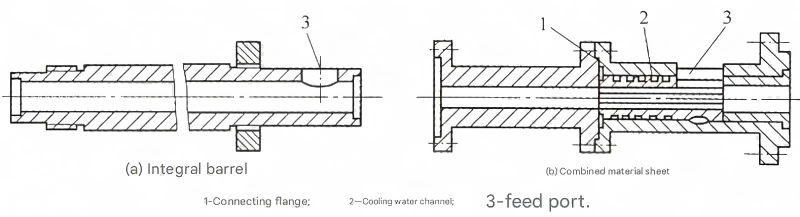
Figure 1: Monolithic and Segmented Barrel Structures
- 1. Connecting flange - provides secure joining of barrel sections in segmented designs
- 2. Cooling water channels - maintain temperature control in critical sections of the extruder machine
- 3. Feed opening - where raw materials enter the extruder machine barrel
Each design presents distinct advantages depending on the extruder machine application. Monolithic barrels excel in applications requiring precise temperature control and uniform material processing, while segmented designs offer greater flexibility for different production requirements.
Grooved Feed Section Design in Extruder Machine Barrels
A significant advancement in extruder machine technology came in the 1970s with the development of barrels featuring tapered inner surfaces with longitudinal grooves in the feed section. This innovation originated from research conducted by Professor G. Menges and his team at the Institute of Plastics Processing (IKV) at RWTH Aachen University in Germany.
Performance Benefits
This specialized design dramatically improved the extruder machine's solid conveying efficiency, increasing it from 0.3-0.5 to 0.6-0.85 while also creating stiffer screw extrusion characteristics. The feed zone in such an extruder machine can reach high pressures of 80-150 MPa, necessitating forced cooling systems.
The cooling water removes substantial heat—equivalent to approximately 14% of the motor power in the extruder machine. For this reason, when screw diameters exceed 120mm, this design is generally not recommended as a method to increase extruder machine output.
The grooved design is particularly effective for materials with poor flow characteristics, significantly enhancing feeding efficiency in the extruder machine.
Figure 2: IKV Barrel with Grooved Feed Section
Grooved inner surface design that revolutionized solid conveying efficiency in the extruder machine
Design Parameters for Grooved Sections
| Parameter | Specification | Notes |
|---|---|---|
| Groove Length | 3-5D for pellets 6-10D for powders |
D = screw diameter |
| Taper Angle | 3°-5° | Optimizes material compression |
| Number of Grooves | Approximately 0.1D | Scales with extruder machine size |
| Cross-Section Shape | Rectangular, Triangular | Depends on material characteristics |
Proper implementation of these parameters ensures optimal performance in the extruder machine, balancing material conveying efficiency with energy consumption and wear characteristics. The grooved design remains a critical innovation in modern extruder machine technology, particularly for specialized applications requiring enhanced feeding performance.
Feed Opening Structures in Extruder Machine Design
The design of the feed opening in an extruder machine determines how materials are introduced into the screw channels. Typically located at the beginning of the extruder machine screw, modern feed sections often feature independent water-cooled jackets integrated with the rest of the barrel structure. This cooling prevents premature polymer temperature rise, which could cause bridging—material forming a blockage above the feed opening—and prevent proper feeding in the extruder machine.
Cooling also prevents the formation of a molten film between the material and barrel wall, which could cause materials to rotate with the screw rather than moving axially—effectively halting solid conveying in the extruder machine.
Figure 3: Feed Opening Cross-Section Designs
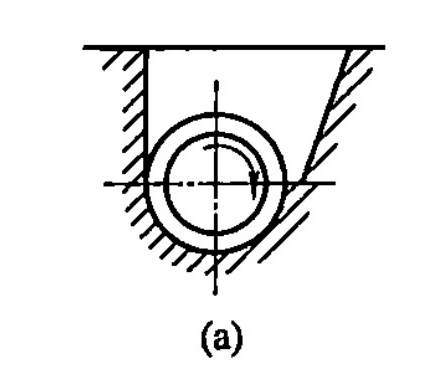
Type (a)
Early design for ribbon materials, unsuitable for powders or pellets
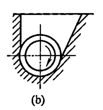
Type (b)
Primarily used for melt-fed extruder machine systems
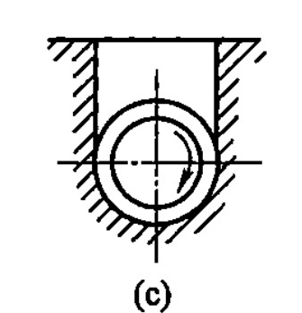
Type (c)
Standard general-purpose design for many extruder machine applications
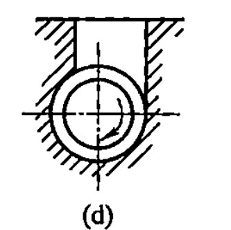
Type (d)
Alternative standard design with modified geometry
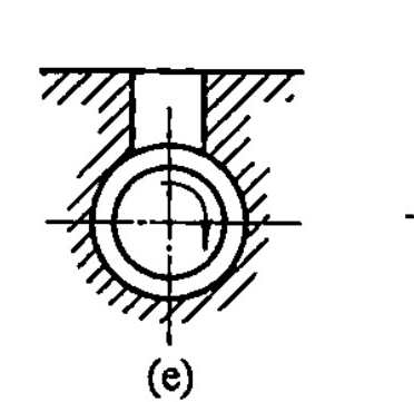
Type (e)
Another general-purpose design variant
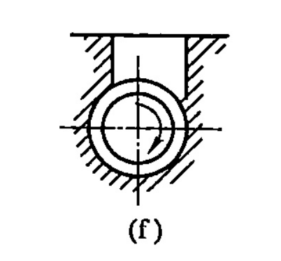
Type (f)
Most successful design with optimal flow characteristics
Common Feed Opening Shapes
-
Rectangular
Long side parallel to barrel axis, typically 1.5-2.0 times the screw diameter in length
-
Square
Symmetric design used in specific extruder machine applications where uniform material distribution is critical
-
Circular
Primarily used with forced-feed systems featuring agitators in the extruder machine
Optimal Design: Type (f)
The Type (f) feed opening has proven most successful in modern extruder machine design. It features one wall perpendicular to the barrel's cylindrical surface and another wall inclined at 45° below. The feed opening's centerline is offset from the screw axis by 1/4 of the barrel diameter.
This configuration optimizes material flow into the screw channels, minimizing bridging tendencies and ensuring consistent feeding—critical factors for maintaining product quality and process stability in the extruder machine.
Proper feed opening design directly impacts extruder machine efficiency, with well-designed systems reducing energy consumption while increasing throughput and process stability.
Breaker Plates and Screens in the Extruder Machine
The breaker plate (or perforated plate) and screen pack function as resistance elements in the extruder machine, converting the spiral material flow into linear motion. These components also equalize extrusion pressure, block incompletely melted materials, and filter contaminants—resulting in a more uniform axial velocity distribution across the material flow in the extruder machine.
Figure 4: Breaker Plate Structure
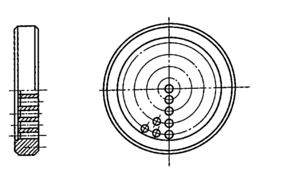
Key Breaker Plate Specifications:
- Thickness: 1/3 to 1/5 of barrel inner diameter
- Hole Diameter: 2-7mm, with chamfers on the feed side
- Hole Arrangement: Concentric circles or hexagonal pattern
- Open Area: 30%-70% of total surface area
- Material: Typically stainless steel
Function and Placement
The breaker plate is positioned at a distance of approximately 0.1D from the screw tip in the extruder machine—close enough to ensure flow stability while preventing material accumulation and degradation. This strategic placement balances pressure development with material residence time in the extruder machine.
A critical function of the breaker plate is supporting the screen pack, which is positioned between the screw tip and breaker plate,紧贴着多孔板。在生产电缆、单丝、透明制品和薄膜等产品时,过滤网在挤出机中起着至关重要的作用。
Coarse screens are typically made of stainless steel mesh, while finer screens may use copper mesh. Screen fineness ranges from 20 to 120 mesh, with filter packs generally consisting of 1-5 layers—coarse screens on the outside and finer screens in the middle in the extruder machine.
The pressure drop across the screen pack provides valuable information about filter condition in the extruder machine, with increasing pressure indicating clogging that necessitates screen replacement.
Continuous Screen Changers
After extended use, filter screens require replacement to remove accumulated contaminants. To improve screen changing efficiency in high-volume production, automatic screen changers are employed in the extruder machine, with effective sealing during the change process being critical.
Figure 5: Continuous Screen Changer
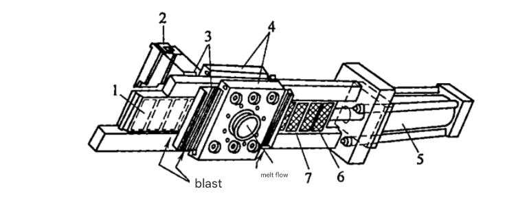
Hydraulically actuated continuous screen changer for uninterrupted extruder machine operation
1. Solidified material forming the sealContinuous screen changers consist of a hydraulic actuation system and the changer mechanism itself. When molten material seeps around the breaker plate area, heaters cool the melt below its viscous flow temperature, creating a 0.05-0.13mm solidified film that forms an effective seal in the extruder machine. This design allows continuous operation with excellent sealing, making it widely used in modern extruder machine applications where uninterrupted production is critical.
Feeding Systems in the Extruder Machine
The feeding system supplies material to the extruder machine, consisting of a hopper and a material transport mechanism. Proper feeding is essential for consistent extruder machine operation, directly impacting product quality and process stability.
Hopper Designs
Water-cooled hopper designs include conical, cylindrical, and cylindrical-conical configurations. Modern extruder machine hoppers feature sight glasses for material level monitoring, bottom gates for stopping or regulating material flow, and covers to prevent contamination from dust, moisture, and other debris.
Figure 6(a): Standard Hopper
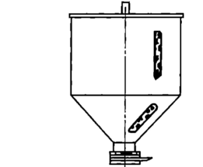
Standard hoppers are constructed from lightweight, corrosion-resistant, easily machined materials—typically aluminum or stainless steel. The capacity is generally sized for 1-1.5 hours of extruder machine operation at maximum throughput.
Figure 6(b): Hot Air Drying Hopper
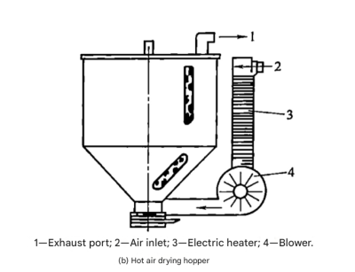
- 1. Exhaust port for moisture removal
- 2. Air inlet for drying medium
- 3. Heating element for air temperature control
- 4. Blower for air circulation
Hot air drying hoppers use blowers to introduce heated air from below, which exits through the top, simultaneously drying the material and increasing its temperature. This preheating accelerates melting rates in the extruder machine while improving plasticization quality—particularly valuable for hygroscopic materials that absorb atmospheric moisture.
Material Loading Methods
Material loading refers to the methods used to transport materials into the extruder machine hopper. Various systems have been developed to suit different material types, production scales, and factory configurations in extruder machine operations.
Pneumatic Conveying
This method uses compressed air to transport materials through pipes to the extruder machine hopper, typically incorporating a cyclone separator to remove air before material enters the hopper.
Pneumatic systems are particularly effective for pellet transport in the extruder machine but may cause segregation with blended materials or damage fragile pellets.
Auger Conveying
Auger conveyors consist of a motor-driven spring or screw within a flexible tube, transporting material through rotational motion to the extruder machine hopper.
Potential drawbacks include spring failure if improperly sized and hose wear, with exposed springs presenting burn hazards if not properly positioned relative to the extruder machine motor.
Other loading methods include vacuum systems, conveyor belts, and manual feeding. While manual feeding may be used for small extruder machine operations, larger production facilities typically employ automated systems like pneumatic or auger conveyors to ensure consistent material supply to the extruder machine.
The selection of appropriate feeding systems depends on material characteristics, production volume, and integration with other extruder machine line components, with automated systems generally offering superior consistency and reduced labor requirements in modern extruder machine operations.
Conclusion
The barrel and its associated components form the critical core of any extruder machine, with each element playing a vital role in material processing and final product quality. From the basic barrel structures to specialized feed sections, and from breaker plates to feeding systems, every component influences the extruder machine's performance, efficiency, and versatility.
Understanding these components and their interactions is essential for optimizing extruder machine operation, troubleshooting issues, and selecting the right equipment for specific applications. As material science and engineering advance, we continue to see innovations in barrel design and related components that enhance the capabilities and performance of the modern extruder machine.
Learn more